
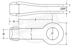
Clevises have to be right hand and left hand threaded when paired with a single rod to allow for tensioning. When used with a turnbuckle, both clevises will need to be ordered with right hand threads only. This creates the only left hand connection to be in the turnbuckle allowing the assembly to be tensioned. When purchasing clevises, the four important dimensions are the clevis number, tap size, grip size, and pin dimension. The clevis size refers to the D dimension and will determine how large of rod can be used and capacity of the assembly. The tap size “W” is the diameter of rod used and should be specified right or left handed thread. The “grip” is the distance between the clevis “ears” and will be wider than the plate that the clevises are fixing to. The pin dimension “P”, is restricted to the size of the clevis in correlation with the size of the rod and can be determined with our pin chart.

| Clevis Size | Dimensions in Inches | Weight w/ Pin, lbs. | Available Strength, kips | Manufacturing Based Constraints | ||||||||
|---|---|---|---|---|---|---|---|---|---|---|---|---|
| Max, W | Max, P | D | N | A | L | T | ASD | LRFD | Min Grip Size | Max Grip Size | ||
|
Dimensions per AISC Manual of Steel Construction thirteenth edition page 15-14 ASD - Allowable Stress Design (according to the AISC 9th Ed.) LRFD - Load and Resistance Factor Design (according to AISC 3rd Ed.) |
||||||||||||
| 2 | 5/8 | 3/4 | 17/16 | 5/8 | 39/16 | 11/16 | 5/16 | 1.5 | 5.83 | 8.75 | 1/2 | 3/4 |
| 21/2 | 7/8 | 11/2 | 21/2 | 1 | 4 | 11/4 | 5/16 | 2.5 | 12.5 | 18.8 | 3/4 | 11/4 |
| 3 | 13/8 | 13/4 | 3 | 11/4 | 51/16 | 11/2 | 1/2 | 5.0 | 25 | 37.5 | 3/4 | 11/2 |
| 31/2 | 11/2 | 2 | 31/2 | 11/2 | 6 | 13/4 | 1/2 | 8.0 | 30 | 45 | 7/8 | 2 |
| 4 | 13/4 | 21/4 | 4 | 13/4 | 515/16 | 2 | 1/2 | 11.0 | 35 | 52.5 | 7/8 | 21/4 |
| 5 | 2 | 21/2 | 5 | 21/4 | 7 | 21/2 | 5/8 | 21.0 | 62.5 | 93.8 | 1 | 23/4 |
| 6 | 21/2 | 3 | 6 | 23/4 | 8 | 3 | 3/4 | 32.0 | 90 | 135 | 1 | 31/2 |
| 7 | 3 | 33/4 | 7 | 3 | 9 | 31/2 | 7/8 | 53.0 | 114 | 171 | 1 | 41/2 |
| 8 | 4 | 41/4 | 8 | 4 | 101/8 | 4 | 11/2 | 80.0 | 225 | 338 | 1 | 5 |
Note: The grip size is normally specified as material thickness +¼”. Grip dimensions are normally called out in ¼” increments.